
This how-to is directed at Exocet Miata owners looking to upgrade and simplify their ignition control system. Motogadget's mo.unit product line is designed for motorcycles, and can be adapted to vehicle use with some creativity.
There is a "basic" mo.unit, without Bluetooth, which is a bit cheaper but lacks some of the more interesting functionality, such as maintenance tracking and keyless ignition/start. I'll leave the decision making, and the budgeting, to you. I bought the Bluetooth model.
Parts list:
- Motogadget mo.unit blue
- Circuit breaker or fuse to protect the Motogadget
You-should-have list:
- Motogadget instruction manual
- Mazda Miata factory wiring schematics for the correct year


Key notes up front
ECU
- This can be used with the stock ECU or with MegaSquirt (or any other aftermarket ECU)
- If using the stock ECU, and the vehicle was originally equipped with an immobilizer (anti-theft) device, you will be unable to utilize the Motogadget keyless start without first bypassing the immobilizer; this how-to doesn't cover this procedure
Motogadget mo.unit
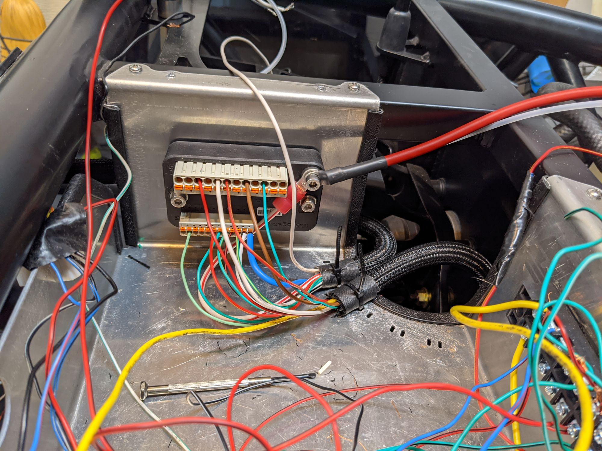
- A 40A (or smaller) circuit breaker (see the picture above) or fuse must be installed between the Motogadget device and the battery
- Almost all inputs are a ground signal, except for "Lock" (connected to the ignition switch) which must be a +12VDC signal
- All outputs are +12VDC
Miata Ignition
The NB Miata ignition switch is +12VDC for both RUN and START but, as you see above, Motogadget expects a ground signal for starting
- You will need to rewire the harness leading to the ignition switch, turn signal switch, headlight switch, brake switch, and maybe the clutch switch, depending on your choices
It really isn't bad, so let's get started. We'll go device-by-device.
Note that all of the supplied color codes are based on the factory wiring harness for a 2004 Mazdaspeed Miata without daytime running lights, so your mileage may vary based on your specific Miata.
Inputs
Lock, Start
The NB Miata ignition switch is +12VDC for both RUN and START, which is in conflict with the Motogadget's expectations for a ground signal for starting. Fortunately, the internals of the ignition switch are comprised of two separate electrical switches, each with their own input wire from the main harness; both inputs are WHT/RED.
Disconnect the ignition switch from the harness and use a multimeter to determine which WHT/RED connects to which electical switch internal to the ignition switch.
Internal switch #1
- WHT/RED input to this switch must be +12VDC (same as factory wiring)
- BLK/WHT output is for the RUN and ACC positions (unused)
- BLU output is for the RUN and START positions, connects to the Motogadget "Lock"
Internal switch #2
- WHT/RED input to this switch must be ground (not the same as factory wiring)
- Option A: factory behavior with the clutch pedal required to start the engine
- Cut this WHT/RED wire where it ties into Switch #2's WHT/RED
- Rewire the clutch switch, also referred to as Starter Interlock Switch
- WHT/BLK input is +12VDC from the factory, and must be grounded
- BLK/RED output (normally connected to the starter) must be connected to the Ignition Switch input for internal switch #2
- Option B: (my choice) clutch not required for starting engine
- Cut this WHT/RED wire where it ties into Switch #2's WHT/RED, add a ring terminal to the WHT/RED from Switch #2, and attach it to a ground screw
- Option A: factory behavior with the clutch pedal required to start the engine
- BLK/RED output is for the RUN position (unused)
- WHT/BLK output is for the START position, connects to the Motogadget "Start"
I used a ground screw on the steering column:

Turn L, Turn R
As you can probably guess, no, the stock wiring of the turn signal switch (which is +12VDC) isn't aligned to Motogadget's needs, but at least it's easy to fix.
- VIO/WHT input must be connected to ground; cut the wire, add a run terminal, and attached it to a ground screw
- GRN/YEL output is for LEFT, connects to the Motogadget "Turn L" input
- BLK/RED output is for RIGHT, connects to the Motogadget "Turn R" input
I used the steering column ground screw pictured above for the ignition switch rewire.
Horn
- GRN/ORG from the clock spring connects to the Motogadget "Horn" input
Brake
The factory brake switch wiring is +12VDC when the pedal is depressed, which is (again) in conflict with Motogadget's expectations.
- WHT/GRN input must be connected to ground; cut the wire, add a ring terminal, and attach it to a ground screw
- GRN output connects to the Motogadget "Brake" input
I used one of the brake pedal assembly bolts for ground.
Light
Motogadget isn't exceptionally flexible in how it accepts inputs related to the state of the headlights. Really there are five different possible states on the Miata: off, parking lights only, low beam, high beam, and flash-to-pass. However, Motogadget only has one ground input to accomplish all of these, so sacrifices must be made if you intend to keep the stock headlight switch.
This doesn't address the stock fog lights, which I'm assuming you're discarding.
The solution I arrived at after Motogadget was installed:
- Headlight switch for off/parking/headlights is ignored
- Headlights (and parking lights) automatically off with ignition on
- Headlights (and parking lights) automatically on after cranking the engine
- Flash-to-pass and high beams (pushing/pulling the headlight stalk) is functional
The stock headlight switch has two internal switches which share a single ground input.
- BLK input must be connected to ground (which is true from the factory)
Internal switch #1, "Headlight Switch"
- LT GRN output is for TNS and HEAD (unused)
- RED/YEL output is for HEAD (unused)
Internal switch #2, "Beam Switch"
- RED/YEL output is for FLASH-TO-PASS (unused)
- RED output is for LOW (unused)
- WHT output is for HI and FLASH-TO-PASS, connected to Motogadget "Light" input
Aux 2
Motogadget can monitor vehicle speed, and from there calculate distance traveled. This is useful in two regards based on Motogadget's wizardry: first, that it will track how "fun" every trip was, as a function of speed and number of corners involved. And second that it can calculate the time between maintenance activities, such as oil changes or brake pad inspections. Note these functions require the Bluetooth version of mo.unit.
- ORG from the speedometer sensor
Outputs
Start
Neither of these are a high current draw, and both are required.
- BLK/RED (originally from the starter interlock switch) leads to the starter
- VIO (originally from the stock fuse panel) leads to the instrument cluster
Turn L, Turn R
Originally these wires would be found leaving the factory flasher control module (under the left side of the dash).
- GRN/BLK to all left-hand turn signals, front and rear
- GRN/WHT to all right-hand turn signals, front and rear
Horn
From the factory there's a horn relay, but that isn't required going forward because Motogadget is the relay.
- BRN (originally the output from the horn relay) leads to the horn
Also, if in doubt, upgrade. There's absolutely nothing wrong with having an airhorn.

Brake
- GRN (originally output wire from the brake switch) leads to the brake lights
Light, Hi Beam
The stock headlights were individually fused, with one fuse for the left headlight (low and high) and a separate fuse for the right headlight (low and high). A creative use of the ground to low and high beams then controlled them. This doesn't work well for Motogadget, so it would be best to cleanly rewire both headlights to ensure proper functionality.
If you do decide to repurpose stock wiring colors (which is what I did), consider the following:
- GRN (originally right headlight) for low beams, both sides
- RED/YEL (originally left headlight) for high beams, both sides
Please note that Aux 1 Output is required for the parking lights.
Also, LED headlights with integrated halo blinkers aren't a terrible way to go.

Ignition
Lots of things need to be connected here: ECU, fuel injectors, and various other engine electronics and sensors
- WHT/RED (originally from the ignition switch) to a +12VDC distribution block
Aux 1
I used the Motogadget functionality of having Aux 1 control the parking lights.
- RED/BLK (originally all parking lights) to whatever parking lights you've retained and to the instrument cluster for backlighting
I recommend sidemarkers wherever possible, and the license plate bolt lights are kinda nifty. You do have license plate lights, right?


Motogadget Settings
Using the mo.ride app, or the manual process for mo.unit basic owners, set the following:
- Handlebar controls: Configuration C
- Tail light: Standard
- Your configuration may differ, but I needed Standard
- Follow the instructions
- Blinkers: No Switch-Off
- Brake light: Permanently Active
- Alarm:
- I'll leave this for you to decide
- Position light: Deactivated
- m.wave: Deactivated
- Light: Garage Light
- Your preference may differ
- Output AUX1: Tail Light
- This is your parking lights
- Output AUX2: Active with Ignition
- I used this to provide more amperage for the +12VDC distribution block
- Kickstand: Deactivated
- To be discussed in another how-to regarding push-button start
- Parklight light: AUX1 permanently active
- Keyless-GO range:
- To be discussed in another how-to regarding push-button start
- I'll leave this for you to decide
- Speedometer input:
- Follow the instructions
- Calibrate:
- This will calibrate the Motogadget to be aware of how much wattage each of your lights (parking, headlight, high beam, blinker, brake) and inform you when it suspects one is burnt out due to a low wattage reading
- Follow the instructions
- As a note:
- I have progressive blinkers, meaning they strobe to the left or to the right when I'm signaling, which results in a variable wattage usage
- Motogadget's calibration function waits for .500 seconds then takes a reading, which may or may not be the low point of each light's wattage consumption
- As a result, I was advised by technical support to disconnect my blinkers entirely before performing a calibration so that my blinkers will never been considered failing by Motogadget
Other Considerations
Reverse Lights
The Motogadget is not designed for reverse since most (yes, most) motorcycles do not have reverse. For you, the reverse position switch on the transmission (also known as the back-up light switch) will need to be wired to your choice of back-up lighting.
On the reverse position switch:
- BLK/YEL is the +12VDC input (originally from the fuse panel) which must be connected to the +12VDC distribution block, fed from the Motogadget Ignition Output
- RED/YEL leads to the back-up light(s)
On the backup lights:
- BLK is ground
Also, for what it's worth, I used a single aftermarket fog light as my reverse light. Works great. Comes in a 2-pack so I officially have a spare.

Wiring tray afterwards
This is with:
- SpeedCircuit Deep Wiring Tray for Exocet (2" deeper than Exomotive's tray)
- Motogadget mo.unit blue
- MSD Solid State Relay Block, P/N 7564
- Stock ECU, immobilizer, and instrument cluster
And without:
- Shortening the engine bay harness
- 40A circuit breaker (shh, it came shortly afterwards)

